Tuesday, December 21, 2010

Coolant Bypass (Cold Start Bypass)

Coolant Bypass Mod
Just about every stock car has a feature called the cold start valve. The cold start valve is located on the bottom of the throttle body and it has two lines that run into it, one in and one out. The lines transfer coolant which in a cold start situation, helps warm up the engine faster by warming up the air in the throttle body via-coolant. In a cold climate(one that has regular temps below freezing) it has a purpose, but in summer months or a climate that doesn't have a winter of freezing temps, the cold start valve hurts hp because hot air is bad air. So you have two lines to modify:
1. The coolant line coming out of the block into the cold start valve, and
2. The coolant line coming out of the cold start valve and back into the block.

The mod is simple: Bypass the valve by running line #1 where line #2 connects back into the block. Now you have coolant going out of the block and back into the block, which is essentially what it did before, but it doesn't go through the throttle body which drastically reduces air temps in the intake manifold. This whole cold start valve is just for warming up a very cold car, but it's not needed in a hot climate. V8 guys have been doing this for years in F-Bodies and Mustangs with all kinds of success. The idle may change, but again, that's life. People have reported up to 8hp at the wheels with this mod alone.


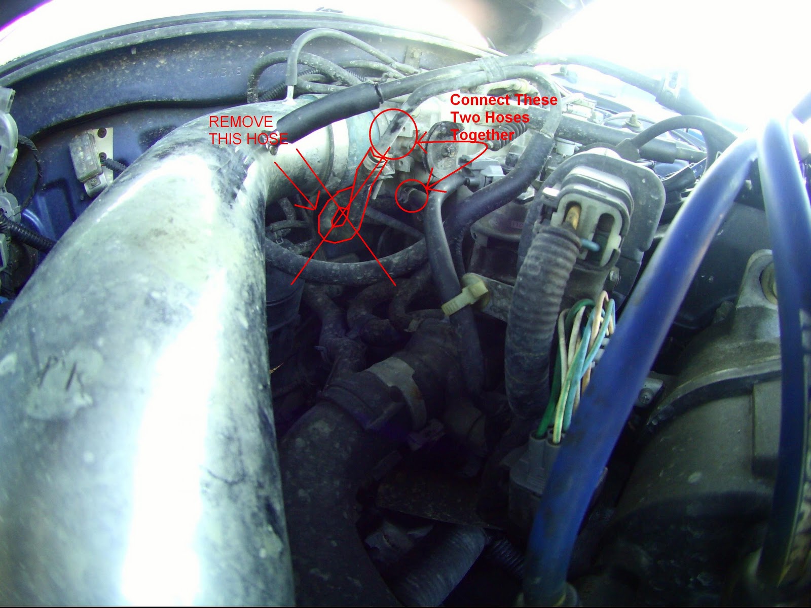
1.) Locate the Inlet & Outlet hose located on the bottom of the throttle body.


2.) Disconnect the hoses here.


3.) After you disconnect the two hoses connect them using either a fitting or the factory piece like I did. Here is another shot with how I set mine up.

I will post the finished product picture in the next day or two since I forgot then it was dark when I realized I didn't have the finished product picture.

Honda factory FPR (fuel pressure regulator) mod

This is a guide on how to modify your factory fuel pressure regulator. People have actually ran better with this mod than when they did with a aftermarket FPR.

Here is a REAL example of the gains from this SIMPLE and cheap mod.

Stock 95 Civic DX(Automatic)
With air box removed - 17.4@80mph
With air box removed and fpr mod - 17.0@80.5mph
1.) Locate your FPR.


2.) Disconnect the vacuum line from the FPR (fuel pressure regulator)


3.) Using a vacuum line cap, cap the line coming from the intake manifold. YOU MUST CAP IT BUT DO NOT CAP THE FPR!! I bought a cap kit from O'Reileys for $8.00 I've been told you may also use a golf tee or a wood screw.


4.) Tuck it somewhere and enjoy your new increase in fuel.

Wednesday, October 20, 2010

Honda ECU List

Code:OBD:VTEC:VTEC Cross-over:Rev Limit:Found In:
P051no

1992-1995 Honda Civic CX
P061no

1992-1995 Honda Civic DX
P071yes

1992-1995 Honda Civic VX
P081yes??
1992-1995 Honda Civic D15B (JDM)
P0A1yes

1994-1995 Honda Accord EX
P0A0no

1990-1995 Honda Accord F22A
P131yes

1992-1995 Honda Prelude VTEC (H22A)
P141no

1992-1995 Honda Prelude Si (H23A)
P271yes

1992-1995 Honda Civic EG JDM1600 SOHC
P281yes450076001992-1995 Honda Civic EX/Si / del Sol Si
p281yes

1992-1995 Honda Del Sol Si/Civic Hatchback Si/ Civic EX
P2E2no

1996-1998 Honda Civic DX
P2M2yes

1996-2000 Honda Civic (NZ) SOHC VTEC
P2N2no

1996-2000 Honda Civic HX
P2P2yes

1996-2000 Honda Civic EX (D16Y8)
P2T2byes

1999-2000 Honda Civic Si
P301yes

1992-1995 Honda del Sol DOHC VTEC EG/SiR
P54-G311yes

1997 Honda Accord 1.8 LS (EDM)
P5P2yes

1996-1999 Honda Prelude (H22A)Type SH / Type S(JDM)
P611yes

1992-1993 Acura Integra GSR (B17A)
P721yes

1994-1995 Acura Integra GSR
P722yes

1996-2000 Acura Integra GSR
P722yes

1996-1999 Acura Integra GSR B18C
P732yes

1996-2000 Acura Integra Type R (JDM and USDM)
P741no

1992-1995 Acura Integra LS/GS
P751no

1992-1995 Acura Integra LS/GS
P752no

1996-2000 Acura Integra LS/GS
PBA2yes

1997-2000 Acura 1.6 EL (Canada)
PCT2yes

1997-2001 Honda JDM ITR/CTR
PCX2byes

1999-2001 Honda S2000
PG60no

1988-1989 Acura Integra, All Models
PM50no

1988-1991 Honda Civic/CRX DX
PM60no

1988-1991 Honda Civic/CRX SOHC Si
PM70no

1988-1991 Honda ZC (JDM EF)
PM80no

1988-1991 Honda CRX HF
PR20no

1988-1991 Honda ZC (EDM)
PR30yes

1989-1991 Acura Integra XSi/RSi
PR3-J000yes

1992 Acura Integra JDM B16A EF 8/9
PR3-J510yes

1992 Acura Integra JDM B16A EF 8/9
PR40no

1990-1993 Acura Integra LS/GS
PR42no

1996-1999 Acura Integra LS/GS/RS (B18B)
PS90no

1988-1991 Honda Civic 4-door EX Automatic
PW00yes

1989-1991 Honda Civic/CRX SiR (or auto from 90-91 Integra XSi)

OBD 0 Wire Colors off HF/Si

OBD 0 Wire Colors off HF/Si

A1- No 1 INJ Gold/Silver DOTS

A2- GRD w/A4 to main relay Black/silver DOTS

A3- No 2 Yellow/silver DOTS

A4- GRD w/A2 to main relay Black/silver DOTS

A5- NO 3 INJ Red/silver DOTS

A6- Purge cut off solenoid HF only Green/silver DOTS

A7- NO 4 INJ Red/silver DOTS

A8- Lock-up control solenoid valve/VTEC

A9 nothing

A10 EGR valve HF only Yellow/red

A11 EACV w/A17 Blue/yellow

A12 MAIN relay w/A14 Green/black

A13 MAIN relay w/A15 Yellow/black

A14 MAIN relay w/A12 Green/black

A15 MAIN relay w/A13 Yellow/black

A16 GRD w/A18 Brown/black

A17 Nothing or B18 IAB Solenoid

A18 GRD w/A18 Black/red

B1 Hazzard/Fuse/Brake switch/No HF

B2 Tandem Valve control Solenoid valve Orange/silver DOTS NO HF OR SIR

B3 FAST Idle valve or A/C Clutch Relay Yellow/Silver DOTS

B4 RADIATOR FAN RELAY Yellow/green NO SIR

B5 ALTERNATOR White/silver or on SIR OIL PRESSURE SWITCH

B6 CHECK ENGINE LIGHT Green/red

B7 Shift position sensor A/T only HF/SI A/C SWITCH w/B8 Green/silver DOTS NO SIR

B8 A/C SWITCH w/B7 Blue/silver DOTS NO SIR

B9 Nothing/COULD BE BRAKE SWITCH for SIR

B10 CRANK ANGLE SENSOR Blue/green

B11 CLUTCH SWITCH (HF ONLY) Green/black OR Rear defogger Switch on SIR

B12CRANK ANGLE SENSOR White/red

B13 NO2 FUSE 10A Blue/white

B14 ALTERNATOR Blue/silver DOTS

B15 IGNITER UNIT w/B17 White/silver DOTS

B16 SPEED SENSOR Yellow/red

B17 IGNITER UNIT w/B15 White/silver DOTS

B18 Nothing

B19 ELD or on SIR KNOCK SENSOR

B20 ING TIMING ADJ CONNECTOR Brown/red

C1 CYLINDER POSITION SENSOR Orange/silver DOTS

C2 CYLINDER POSITION SENSOR White/silver DOTS

C3 TDC SENSOR Orange/black

C4 TDC SENSOR White/blue

C5 TA SENSOR Red/orange

C6 TW SENSOR Red/white

C7 THROTTLE ANGLE SENSOR Red/blue

C8 SECOND O/2 SENSOR For B16A

C9 PA SENSOR Red/white or ON SIR P/S OIL SWITCH

C10 BRAKE AND REVERSE LIGHTS (HF ONLY) Green/white OR on SIR BRAKE SWITCH

C11 MAP SENSOR White/brown

C12 THROTTLE ANGLE SENSOR Green/white

C13 THROTTLE ANGLE SENSOR White/yellow

C14 MAP SENSOR Green/white

C15 MAP SENSOR Yellow/red

C16 #1 O/2 SENSOR White/silver DOTS

Honda OBD-0 DPFI to MPFI Comparison Pinouts

OBD0 DPFI to MPFI Comparison Pinouts


DPFIMPFI
Pin#Wire ColorFunctionWire ColorFunction
A1Yellow 2Aux InjectorBrown#1 Injector
A2Black 1Main Relay/GroundBlack 1Main Relay/Ground
A3Yellow 1Aux InjectorRed#2 Injector
A4Black 2Main Relay/GroundBlack 2Main Relay/Ground
A5Red 2Main InjectorLight Blue#3 Injector
A6GreenPurge Cut Off Solenoid Valve (Coil)GreenPurge Cut Off Solenoid Valve (Coil)
A7Red 1Main InjectorYellow 1#4 Injector
A8Yellow 3Sedan LX A/T

A10RedEGR Solenoid Control Valve (Coil) (A/T only)

A11Blue/YellowEACV (Coil)Blue/YellowEACV (Coil)
A12Green/Black 2Main RelayGreen/Black 2Main Relay
A13Yellow/Black 2Main RelayYellow/Black 2Main Relay/Injector Resistor Box
A14Green/Black 1Main RelayGreen/Black 1Main Relay
A15Yellow/Black 1Main RelayYellow/Black 1Main Relay/Injector Resistor Box
A16Brown/BlackGroundBrown/BlackGround
A17


A18Black/RedGroundBlack/RedGround

Pin#Wire ColorFunctionWire ColorFunction
B1White/GreenHazard FuseWhite/GreenHazard Fuse
B2OrangeTandem Control Solenoid ValveBlue 1Fast Idle Control Solenoid Valve
B3YellowA/C Clutch RelayYellowA/C Clutch Relay
B4Yellow/GreenRadiator Fan RelayYellow/GreenRadiator Fan Relay
B5White/YellowAlternatorWhite/YellowAlternator
B6Green/OrangeCheck Engine Warning LightGreen/OrangeCheck Engine Warning Light
B7Green/OrangeA/T Shift Position Console Switch (Park, Neutral)

B8Blue/RedA/C SwitchBlue/RedA/C Switch
B9


B10

OrangeCrank Angle Sensor
B11Green/BlackA/T Shift Position Console Switch (Drive)

B12

WhiteCrank Angle Sensor
B13Blue WhiteMain RelayBlue WhiteMain Relay
B14Blue 2To Yellow, To AlternatorBlue 2Alternator
B15White 1Ignitor UnitWhite 1Ignitor Unit
B16Yellow/RedSpeed SensorYellow/RedSpeed Sensor
B17White 2Ignitor UnitWhite 2Ignitor Unit
B18


B19Green/RedElectric Load DetectorGreen/RedElectric Load Detector
B20BrownIgnition Timing Adjusting ConnectorBrownIgnition Timing Adjusting Connector

Pin#Wire ColorFunctionWire ColorFunction
C1OrangeCrank Angle SensorBlue/GreenCylinder Position Sensor
C2White 4Crank Angle SensorBlue/YellowCylinder Position Sensor
C3Orange/BlueTDC SensorOrange/BlueTDC Sensor
C4White/BlueTDC SensorWhite/BlueTDC Sensor
C5Red/YellowTA SensorRed/YellowTA Sensor
C6Red/White 1TW SensorRed/White 1TW Sensor
C7Red/BlueThrottle (Position) Angle Sensor (TPS)Red/BlueThrottle (Position) Angle Sensor (TPS)
C8YellowEGR Lift Valve Sensor

C9Red/White 2PA SensorRed/White 2PA Sensor
C10Green/White 3Brake SwitchGreen/White 3Brake Switch
C11White 1MAP SensorWhite 1MAP Sensor
C12Green/White 2EGR Lift Valve Sensor/Pa Sensor/Ignition Timing Adjusting Connector/TA Sensor/TPS Sensor/TW SensorGreen White 2Pa Sensor/Ignition Timing Adjusting Connector/TA Sensor/TPS Sensor/TW Sensor
C13Yellow/WhiteEGR Lift Valve Sensor/Pa Sensor/TPS SensorYellow/WhitePa Sensor/TPS Sensor
C14Green/White 1MAP SensorGreen/White 1MAP Sensor
C15Yellow/RedMAP SensorYellow/RedMAP Sensor
C16White 3O2 SensorWhite 3O2 Sensor

Honda OBD 1 & 2 ECU Pinouts

OBD 1 and 2 Honda ECU Pinouts

OBD2aOBD2bFunctionOBD1ColorNotes
A01B05Injector 4A02Yellow
A02B04Injector 3A05Light Blue
A03B03Injector 2A03Red
A04B11Injector 1A01Brown
A05A08SO2H

No connection on OBD1
A06C01PO2HA06Orange/black
A08B12VTSA04Orange/White
A09B20LG1A26Black/Red
A10B02PG1A23Black
A11B01IGP1A25Yellow/Black
A12B23IACVA09Green/White
A15A06PCSA20Red
A16A16FLRA07Green/Yellow
A17A17ACCA15Black/Red
A18A18MILA13Green/Orange
A19A02ALTCA16White/YellowNo connection on D16Y8 P2Nb
A20B13ICMA21Red/Green
A22B22LG2B02Brown
A23B10PG2A24Black
A24B09ICP2B01Yellow Black
A27A20FANCA12Yellow/Green
C01C31CKFP

No connection on OBD1
C02C08CKPPB15Blue/Green
C03C20TDCPB13Orange/Blue
C04C29CYPPB11Orange
C05A27ACSB05Blue/Red
C06A24STSB09Blue/White
C07A10SCSD04Brown
C10B21VBUD01White/Blue
C11C22CKFM

No connection on OBD1
C12C09CKPMB16Blue/Yellow
C13C21TDCMB14White/Blue
C14C30CYPMB12White
C15C10VTMD06Orange/GreenConnected to VTS on OBD2a
C16A26PSWB08Brown/Red
C17C05ALTFD09PinkNo connection on D16Y8 P2Nb
C18C23VSSB10Yellow/Blue
D01C27TPSD11Pink/Black
D02C26ECTD13Red/White
D03C17MAPD17Pink/White
D04C19VCC1D19Yellow/Green
D05A32BKSMD02Greem/White
D06C03KSD03Red/GreenNo connection on P08, P28
D07C16PO2SD14White
D08C25IATD15

D10C28VCC2D20Yellow/White
D11C18SG2D22Green/White
D12C07SG1D21Green/Blue
D14A23SO2S

No connection on OBD1
D16A30ELD10Green/RedNo connection on D16Y8 P2Nb

Honda OBD 0 ECU Pinouts

   Here are the OBD-0 Honda ECU pinouts.  
Pinout'88 HF/Si'90-1 DX (Std.)'90-1 HF/Si'89-92 EF8/9 SiR
A1No.1 INJAux INJ w/A3No.1 INJNo.1 INJ
A2GRD w/A4 to Main RelayGRD w/A4 to Main RelayGRD w/A4 to Main RelayGRD w/A4 to Main Relay
A3No.2 INJAux INJ w/A1No.2 INJNo.2 INJ
A4GRD w/A2 to Main RelayGRD w/A2 to Main RelayGRD w/A2 to Main RelayGRD w/A2 to Main Relay
A5No.3 INJMain INJ w/A7No.3 INJNo.3 INJ
A6 Purge Cut-Off Solenoid ValvePurge Cut-Off Solenoid ValvePurge Cut-Off Solenoid Valve (HF Only)Purge Cut-Off Solenoid Valve
A7No.4 INJMain INJ w/A5No.4 INJNo.4 INJ
A8Lock-up Control Solenoid ValveLock-up Control Solenoid ValveLock-up Control Solenoid ValveSpool (VTEC) Solenoid Valve
A9----
A10-EGR Valve (CA A/T Only)EGR Valve (HF Only) Pressure Regulator Cut-Off Solenoid Valve
A11 EACV w/A17EACV w/A17EACV w/A17EACV
A12 Main Relay w/A14Main Relay w/A14Main Relay w/A14Main Relay w/A14
A13Main Relay w/A15Main Relay w/A15Main Relay w/A15Main Relay w/A15
A14 Main Relay w/A12Main Relay w/A12Main Relay w/A12Main Relay w/A12
A15 Main Relay w/A13Main Relay w/A13Main Relay w/A13Main Relay w/A13
A16 GRD w/A18 GRD w/A18GRD w/A18GRD w/A18
A17 EACV w/A11---
A18 GRD w/A16 GRD w/A16GRD w/A16GRD w/A16
B1Hazard Fuse w/Brake SwitchHazard Fuse w/Brake Switch-Hazard Fuse w/Brake Switch
B2Tandem Valve Control Solenoid ValveTandem Valve Control Solenoid Valve--
B3A/C Clutch RelayA/C Clutch RelayFast Idle ValveA/C Clutch Relay
B4Radiator Fan RelayRadiator Fan RelayRadiator Fan Relay-
B5AlternatorAlternatorAlternatorOil Pressure Switch
B6Check Engine LightCheck Engine LightCheck Engine LightCheck Engine Light(10A)
B7Shift Position Sensor (A/T Only)Shift Position Sensor (A/T Only)A/C Switch w/B8-
B8A/C SwitchA/C SwitchA/C Switch w/B7A/C Switch
B9---Brake Switch
B10--Crank Angle SensorCrank Angle Sensor
B11Shift Position Sensor (AT Only)Shift Position Sensor (AT Only)Clutch Switch (HF Only)Rear Defogger Switch
B12--Crank Angle SensorCrank Angle Sensor
B13No.2 Fuse (10A)No.2 Fuse (10A)No.2 Fuse (10A)No.2 Fuse (10A)
B14AlternatorAlternatorAlternatorAlternator
B15Igniter Unit w/B17Igniter Unit w/B17Igniter Unit w/B17Igniter Unit w/B17
B16Speed SensorSpeed SensorSpeed SensorSpeed Sensor (Electrical)
B17Igniter Unit w/B15Igniter Unit w/B15Igniter Unit w/B15Igniter Unit w/B15
B18----
B19ELDELDELDKnock Sensor
B20Ign. Timing Adj. ConnectorIgn. Timing Adj. ConnectorIgn. Timing Adj. ConnectorIgn. Timing Adj. Connector
C1Crank Angle SensorCrank Angle SensorCylinder Position SensorCylinder Position Sensor
C2Crank Angle SensorCrank Angle SensorCylinder Position SensorCylinder Position Sensor
C3TDC SensorTDC SensorTDC SensorTDC Sensor
C4TDC SensorTDC SensorTDC SensorTDC Sensor
C5TA SensorTA SensorTA SensorTA Sensor
C6TW SensorTW SensorTW SensorTW Sensor
C7Throttle Angle SensorThrottle Angle SensorThrottle Angle SensorThrottle Angle Sensor
C8-EGR Valve Lift Sensor (CA A/T Only)-O2 Sensor B
C9PA SensorPA SensorPA SensorP/S oil switch
C10Brake SwitchBrake SwitchBrake and Reverse Light Switch (HF Only)Brake Switch
C11MAP SensorMAP SensorMAP SensorMAP Sensor
C12PA SensorPA SensorThrottle Angle SensorThrottle Angle Sensor
C13PA SensorPA SensorThrottle Angle SensorThrottle Angle Sensor
C14MAP SensorMAP SensorMAP SensorMAP Sensor
C15MAP SensorMAP SensorMAP SensorMAP Sensor
C16O2 Sensor AO2 Sensor AO2 Sensor AO2 Sensor A    

Honda Throttle Body Size Chart

Below is ALL D/B/H/F series Honda engines factory throttle body sizes. This chart can be used to cross reference when doing a throttle body swap from another engine to save money instead of buying a after-market one.

Engine          TB Size (MM)

D15B7 -               56 MM
D16A6 -               55 MM
D16Y7 -               56 MM
D16Y8 -               56 MM
D16Z6 -               56 MM
ZC -                     55 MM
B16A1 -               55 MM
B16A8                 55 MM
B18C1                 60 MM
B18C5                 62 MM
B18A                   58 MM
B18B                   60 MM
B16A SiR             58 MM
B16A Sir2           60 MM
B16A2                60 MM
B16A3                60 MM
B20B                  60 MM
B20Z                  60 MM
H22A                  60 MM
H23A                  60 MM
F20C                  62 MM
F22                    60 MM
F23                    60 MM

A20A3 Diamond Pistons Order Specs

These specs were posted by "bobafett" of the 3geez.com forums. These specs are for custom low compression pistons for the A20 engine. The pistons ran one guy about $660 with rings.

These specs are for reference only for a future boost build up.

Custom Piston Specs: Job # 22507
----------------------------------------
Bore: 3.307" (remember, this is +.050 overbore)
Compression Height: 1.167
Effective Volume: -11.9
Intake Valve Depth: .125
Exhaust Valve Depth: .077
----------------------------------------
Top Ring: 1.2M
2nd Ring: 1.2M
Oil Ring: 2.8M
----------------------------------------
Lock Ring Decription: SPIROLOX DBL
Lock Ring Part Number: #01-5000
Wrist Pin Diameter: .827"
Wrist Pin Length: 2.500"
----------------------------------------
Piston Weight: 328 Grams
----------------------------------------
Note: Install these pistons with .0040 clearance measured 90 degrees to the pin hole @ .850"

----------------------------------------
----------------------------------------
----------------------------------------
Custom Piston Information: (These are the numbers that were sent to Diamond for them to make my pistons)
----------------------------------------
Finished Bore Size: 3.307" (big)
Stroke: 3.583"
Rod Length: 5.394"
Compression Distance: 1.167"
Block Deck Height: 8.352"
Desired Piston to Deck: 0
Piston Type: Dish
Ring Groove Info:
Top:
1.2mm
2nd: 1.2mm
Oil: 2.8mm
Radial Widths:
Top: .125"
2nd: .144"
Oil: .105"
Support Rail: Yes - 019012276
Rings With Order: Yes
Part Number:
CR-3794 (STD)
----------------------------------------
Wrist Pin Info:
Diameter:
.827"
Length: 2.500"
Pins With Order: 4130 (std)
Wall Thickness of Pin: .145
----------------------------------------
Pin Lock Type:
Double Spiral: .042"
----------------------------------------
Other Order Info:
Quantity: 4
Engine Type: Honda
Application: Street/Strip
Desired Compression Ratio: 8.5:1
Cylinder Head: 12v A20A
Casting #: PJ0 / HF7
Chamber Volume: 47.6cc
Comp. Gasket: .050"
Gasket Bore Dia.: 3.340"
Known Gasket Volume: 7.1cc
Rod Info:
Material:
Steel
Small End Width: .785"
Thickness Above Pin: .203"
Piston Material: 2618
Skirt Shape: Ribbed Side Relief
-----------------------------------------
Misc Engine Information:
Approx Engine Only HP:
150
Combined HP: 350
Power Adder Information:
Type:
Turbo
Pressure Max: 20 psi
Fuel Type: Gasoline
Octane Rating: 91 Minimum
Notes: .180 Crown Min. Brushed Rod.
-----------------------------------------
-----------------------------------------
-----------------------------------------
-----------------------------------------
Compression Ratio Calculator Results:
Number of Cylinders: 4
Bore: 3.3070"
Stroke: 3.5830"
Rod Length: 5.3940"
Gasket Bore: 3.340"
Comp. Gasket: .050"
Block Deck Height: 8.3520"
Top Ring Down: 0.210" ------ 20PSI Boost
Chamber Volume: 47.6
Dome(-) Dish(+): 12.00"
Piston / Deck: 0.000"
Calculated Values:
Total Volume:
571.78
Cylinder Volume: 504.32
Clearance Volume: 67.45
Gasket Volume: 7.18
Top Ring Volume: 0.68
Deck Volume: 0.00
Piston Top Land: 3.269
1/2 Stroke: 1.792
Comp Height: 1.167
Cubic Inches: 123.10
Compression Ratio: 8.48:1
-----------------------------------------
-----------------------------------------

Base Engine Inputs:
Bore:
3.3073"
Stroke: 3.583"
Cylinders: 4
Rod Length: 5.394"
Deck Height: 8.3582"

Chamber / Piston Inputs:
Chamber CC's In Head:
47.6
Piston Design: Flat Top w/valve relief (i have dished pistons, they probably don't need this for their calculations to work)
Valve Reliefs: 12cc's
Gasket Thickness: .050"
Gasket Bore Diameter: 3.340"
Deck Height Clearance: 0.00"
Piston Ring Depth: 0.21"
Piston Top OD: 3.236"
Compression Height: 1.173"

Calculated Results:
Cylinder Size:
30.78 cubic inches / 504.5 cc's / 0.505 liters
Engine Size: 123.12 cubic inches / 2018 cc's / 2.018 liters
Chamber Size: 4.15 cubic inches / 68 cc's / 0.068 liters
Compression Ratio: 8:41
Bore/Stroke Ratio: .923
Rod/Stroke Ratio: 1.505

Volume Contributions:
Head Chamber:
2.904 cubic inches / 47.6 cc's / 70% of total
Gasket: 0.438 cubic inches / 7.18 cc's / 10.6% of total
Deck: 0 / 0 / 0
Valve Reliefs: 0.732 cubic inches / 12 cc's / 17.6% of total
Piston OD: 0.077 cubic inches / 1.26 cc's / 1.9% of total

Tuesday, October 19, 2010

1986-1987 Accord A20A3 ECU Pinout

For reference for people who plan on doing engine swaps or ECU swaps in their 3rd gen Accord here is the 86-87 EFI pinouts:

 Connector "A"

PinUnitWire Color
A1Injector #1Brown
A2GroundBlack
A3Injector #2Red
A4GroundBlack
A5Injector #3Blue
A6Fuel Pump RelayGreen-Black
A7Injector #4Yellow
A8Cold Advance SolWhite
A9N/AN/A
A10EGR Control SolRed
A11N/AN/A
A12Fuel Pump RelayGreen-Black
A13Main Relay Input (Batt)Yellow-Black
A14A/T Idle Control SolGreen
A15Main Relay Input (Batt)Yellow-Black
A16GroundBrown-Black
A17Power InputWhite-Yellow
A18GroundBlack-Red

Connector "B"

PinUnitWire Color
B1A/C Idle Control SolRed
B2N/AN/A
B3N/AN/A
B4Fast Idle Control SolRed-Green
B5N/AN/A
B6PGMFI Ind LightGreen-Red
B7Gear Sel SwitchLt Green
B8A/CBlue-Red
B9Gear Sel SwitchGreen-White
B10N/AN/A
B11N/AN/A
B12N/AN/A
B13Starter InputBlue-Red
B14ALT RF InputWhite-Red
B15N/AN/A
B16N/AN/A
B17N/AN/A
B18Speed SensorYellow
B19N/AN/A
B20N/AN/A

Connector "C"


PinUnitWire Color
C1Cyl SensorOrange
C2Cyl SensorWhite
C3TDC SensorOrange-Blue
C4TDC SensorWhite-Blue
C5Intake Air Temp SensWhite-Red
C6Coolant Temp SensYellow-Green
C7TPS InputRed-Yellow
C8EGR Sensor InputYellow
C9Atmosphere Pres SensRed
C10N/AN/A
C11Map SensorWhite-Blue
C12Sensor Ground 2Green-White
C13VCC2Yellow-White
C14Sensor Ground 1Blue-White
C15VCC1Red-White
C16Oxygen SensorWhite


Monday, October 18, 2010

Climate Control LED Change/Replace!


Those climate control lights looking dim? Wish that the A/C LED was blue? Wish the heat one was red? Well follow this guide and it can come true!

What you need:

Soldering iron - I use a Radio Shack one that I bought for around $5 bucks.
Desoldering tool - I used one I bought at Radio Shack for pretty cheap.
LEDs - You can buy these at Radio Shack as well. Around $5 bucks for a pack!


Step 1:
Remove the circuit board from the casing exposing the LEDs and their soldering locations.


Step 2:
De solder the old LEDs. Then re solder in the new LEDs. This is a pretty simple modification/upgrade/repair that ALOT of people neglect!


Here are two more pictures. One of the lights you are changing and the other of the solder points.


Have fun! Enjoy your newly restored lights. Warning do not attempt to do this unless you know how to solder. iBuilt Racing takes no responsibilities for ANYTHING that may occer during this modification.

Sunday, October 3, 2010

A20 (88-89) Accord Accel coil installation

Step 1:
Remove old coil pack


Step 2:
Cut wires off the two connectors. Keep in mind that black/yellow wires are positive and the blue wires are grounds.

Step 3:
Mount the Accel or MSD coil in the factory coils location. I used black zip tires to hold it in place until I purchase the MSD Blaster SS coil bracket.

Step 4:
Connect the two black and yellow wires to the positive end of your new coil and the blue wires to the negative end. Use a connector from any electrical kit that has a circular connector.

More pictures of the connectors and mounting coming soon. Also note that the wire I'm using to connect the coil to the dizzy is a Accel 8mm that comes in any Accel wire kit.

88-89 Accord "clear" bumper turn signal mod

This will only work for 1988-1989 Honda Accords or other cars that have a separate piece amber piece inside the lens. You can tell by looking at your lenses. If the lens is solid amber then this mod cannot be performed. However, if it is clear then has an insert follow these steps.

Step 1:
Remove the outter lens cover. You may need to use a razor or bake them at 400 degrees for 15 minutes to separate the glue.

Step 2:
Remove the amber insert

Step 3:
Reinstall the lens cover and seal with a rubber sealant such as RTV. Finished product is on the right and the original for reference is on the left.